J. A. Lines, K. van Driel, J. J. Cooper
A wide range of electronic dog training collars (e-collars) is available in the UK, but information enabling purchasers to compare the important characteristics of these collars is not available. In this research, the electrical characteristics of 13 e-collar models were examined, and an approach to ranking the strength of the electrical stimuli was developed. To achieve this, the electrical impedance of dogs’ necks were measured so that e-collars could be tested under realistic conditions. This impedance was found to be about 10 kΩ for wet dogs and 640 kΩ for dry dogs. Two replicates of eight e-collar models and single copies of a further five models were then examined. The stimuli generated by these collars comprised sequences of short high-voltage pulses. There were large differences between e-collar models in the energy, peak voltage, number of pulses and duration of the pulses, but little variation between the replicates. The peak voltage varied with the impedance, from 6000V at an impedance of 500 kΩ to 100V at 5 kΩ. The highest voltages were generated for a few millionths of a second. Stimulus energy levels at the maximum strength setting with a 50 kΩ load ranged from 3.3 mJ to 287 mJ. A stimulus strength ranking indicator was then developed to enable the strengths of e-collars with diverse electrical characteristics to be ranked. This ranking shows a wide range in the stimulus strengths of collars, and that the relationships between ‘momentary’ and ‘continuous’ stimuli for various models differ significantly.
Introduction
Despite substantial interest and concern about electronic training collars (‘e-collars’) for dogs, little information is available about the nature, strength or repeatability of the stimuli they generate. This lim- its attempts to compare collars and to interpret dog responses properly.
E-collars are widely available through shops and the internet. An internet search in 2007 found 170 models marketed under 14 different brand names available for purchase in the UK. All these collars were able to deliver an electrical stimulus to the neck of a dog in response to a radio signal from a remote control handset. Other types of train- ing collars are also available, including those that deliver non-electric stimuli, such as vibration or aerosol sprays, and those that automati- cally deliver an electrical stimulus in response to barking or leaving a defined area. These were outside the scope of the investigation.
Most e-collars have three functions which can be individually con- trolled from the handset. These are: (1) a tone or vibrator, (2) a ‘nick’ or ‘momentary’ electrical stimulus and (3) a ‘continuous’ electrical stimu- lus, which lasts for as long as the button on the handset is pressed, but usually limited to less than 15 seconds.
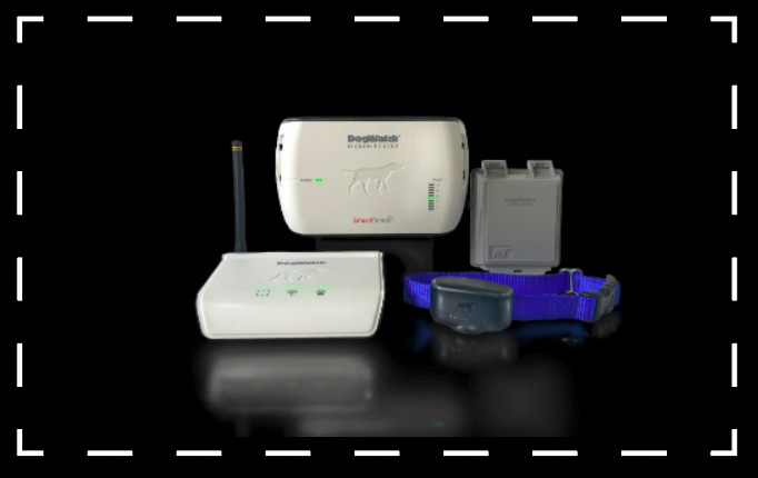
The collar units are typically 50–70 mm long, and 30–40 mm wide and deep. They are attached to a collar and have two stainless steel electric probes which protrude through the collar to make contact with the dog’s throat. These probes are 30–50 mm apart, 10–15 mm long and about 5 mm diameter with smooth rounded ends. Longer probes may be supplied for dogs with thick fur. The remote control handsets have a communication range of between 50 m and 3 km and usually have four controls, one button for each of the three stimuli and a dial or pair of buttons to select the stimulus strength.
Information available at purchase is normally limited to the com- munication range of the handset and manufacturers’ claims about the suitability of the e-collar for dogs of a certain breed, size or demeanour. No information about the electrical stimuli that would enable e-collars to be compared in a meaningful way is given.
In this investigation, the stimulus strengths of e-collars were meas- ured and compared. This was achieved by a series of investigations. First, a technique was developed to measure the electrical impedance of dogs exposed to e-collar stimuli. Then the electrical impedance characteristics of 27 dogs were measured. Next, 21 e-collars were test- ed and characterised using the dog impedances identified. Four human volunteers then experienced samples of these stimuli and ranked their perceived strength. These results and earlier published research were used to identify an algorithm for ranking the perceived strengths on the basis of their voltage, duration and repetition. The use of human subjects at this stage is justified on the assumption that dogs are likely to rank the strength of these short stimuli in ways similar to human subjects even though they may rate them very differently. The rank- ing algorithm was then used to examine the stimuli produced by the collars using their middle and maximum strength settings for both ‘momentary’ and ‘continuous’ stimuli.
Electrical impedance of dogs
The impedance of a dog’s neck between the contact points of the e-collar significantly affects the voltage and current delivered by the
Veterinary Record (2013)
- A. Lines, BSc, MSc, PhD, MIMechE, CEng, Silsoe Livestock Systems, Wrest Park, Silsoe, Bedford, MK45 4HS, UK K. van Driel, BSc, MSc, Formerly at Food and Environment Research Agency, Sand Hutton, York YO41 1LZ, UK J. J. Cooper, BSc, PhD, Animal Behaviour Cognition and Welfare Group, School of Life
doi: 10.1136/vr.101144
Sciences, University of Lincoln, Lincoln LN2 2LG. UK;
E-mail for correspondence: [email protected]
Provenance: Not commissioned; externally peer reviewed.
Accepted December 19, 2012
10.1136/vr.101144 | Veterinary Record | 1 of 7
Downloaded from veterinaryrecord.bmj.com on January 13, 2013 – Published by group.bmj.com
collar. Electrical impedance has two components, an in-phase (resis- tive) component and an out-of-phase (inductive or capacitative) com- ponent. When presented with a high resistive impedance, such as 1 MΩ, some collars generate peak voltages in excess of 6kV, while with an impedance of 500 Ω the same collar may generate a peak voltage of only 20V. Despite the importance of impedance for the electrical out- put of e-collars, it does not appear to have been directly measured. Klein (2000, 2006) estimated resistance of dogs based on measure- ments of pig and human skin. He concluded that a dry dog was likely to present a resistance greater than 80 kΩ and a wet dog 20–40 kΩ. Lindsay (2005) follows Dix 1991 in using a value of 500 Ω, while an expert witness in an Australian court case expected this value to be in the order of 100 Ω (NAIA 2012).
In this investigation, direct measurements of the impedance of the dogs’ necks were made. Since biological materials seldom have linear impedance characteristics, the measurements were made under volt- age conditions similar to those which occur with e-collars. A commer- cial electronic collar was modified for the purpose. In its unmodified state it delivered a ‘momentary’ stimulus comprising eight short volt- age pulses in quick succession. Each pulse lasted 1ms, and the interval between the pulses was 16 ms. This collar was altered to allow only one of these voltage pulses to be delivered, and to enable both voltage and current to be measured. Tests on human volunteers indicated that this modification significantly reduced the perceived strength of the stimulus to a level where it was not considered painful. They also showed that when the pulse sequence was not interrupted there was no significant variation in electrical impedance of the skin between the first and subsequent pulses. This approach enabled impedance to be measured on dogs at representative voltages without administering a full electrical stimulus. Technical details of the measurement and analysis method are given in Appendix 1.
The electrical impedances of 27 dogs were measured. The meas- urements were approved by the relevant institutional ethical review panels, and discussed in detail with the local Home Office Inspector who was satisfied that it did not require a project licence under the Animals (Scientific Procedures) Act 1986. All the dogs were privately owned and were volunteered by their owners who gave informed con- sent and, in most cases, interacted with their dogs during the meas- urement session. Inclusion criteria for the trial included that the dogs had a known background history, were over six months old, readily played or interacted with people, were not nervous, fearful or aggres- sive and had not been trained with e-collars. These conditions were to help safeguard the dog’s welfare. The dogs comprised four spaniels, 10 labradors and other retrievers, seven terriers, two German shepherd dogs, and four other dogs of working breed. Their sex, status, age, hair length, body condition, neck circumference and height were meas- ured. Where possible, six single-pulse stimuli were applied to each dog: three when the coat was dry and three when it was wet. To pro- vide distraction from the potentially perceptible stimulus, dogs were enticed to play or otherwise interact with their owner or a researcher while the single-pulse stimuli were applied (Notermans 1966, Kleiber and Harper 1999). After every single-pulse stimulus, an assessment was made as to whether there had been any behavioural response from the dog which might indicate discomfort or pain. If any such responses were noted by the project team or owner then the sessions with that dog were stopped.
Sixty-four useable measurements were made on the 27 dry dogs, and 53 measurements were made on 22 wet dogs. In the majority of cases, the dogs did not react when the single-pulse stimulus was applied. Where they did react, their responses were limited to ear or eye movement, momentary attention redirection, and in one case both licking of lips and reluctance to re-engage in play. While these behaviours may have been a reaction to the single-pulse stimulus, the stimulus was also always preceded by a tone, and some dogs showed similar reactions (except lip licking) to the tone alone. In the dog which exhibited lip licking and reluctance to re-engage in play, the sessions were discontinued; in all other instances, sessions were con- tinued by agreement of all present. The number of measurements col- lected is lower than the number of stimuli applied, since stimuli were also required to select the measurement range of the equipment. There are fewer wet measurements than dry measurements because the dry
2 of 7 | Veterinary Record | 10.1136/vr.101144
measurements were made first and some dogs lost interest in play or interaction during the test session. This was taken as a sign of disinter- est rather than pain, fear or distress, as it did not occur immediately after the single-pulse stimulus was applied.
The results indicated that the impedance of the dogs could be described as a simple resistive load without a significant capacitive or inductive component. The distribution of values was highly skewed, so median values and percentiles were identified rather than mean values. For dry dogs, the median impedance was 640 kΩ, and the 10th and 90th percentile values were 22 kΩ and 950 kΩ, respectively. For the wet dogs, the median value was 10 kΩ, and the 10th and 90th percentile values were 4 kΩ and 150 kΩ, respectively. For some dogs, there was little variation between the replicate measurements, while others resulted in very different values. The median ratio of lowest to highest measured resistance was 1.8 and 1.7 for dry and wet dogs, respectively. This variation was probably due to changes in the con- tact area and amount of hair between the probes and the skin that occurred as the dog played. Similar changes are likely to occur when a collar is in normal use.
The high impedance presented by dry dogs was probably due to the properties of dog hair, the air gaps between the hairs, the layer of grease covering the skin and the high resistance of dry epidermal skin layers. The finding that resistance was lower in wet dogs is con- sistent with Klein (2006) and Lindsay (2005) as well as human data (IEC 2005). It was likely to be due to improved electrical conduction through wet hair using water pathways, and larger area of contact with the skin due to conduction of the electricity through the surface moisture on the skin surface.
Because of the variation between successive measurements and the small number of replicates, it was not possible to determine whether the resistance of individual dogs differed significantly. No significant trends between resistance and any of the measured fac- tors, such as dog size, neck circumference or hair length and could be identified.
Electronic properties of collars
Thirteen different e-collar models from nine brands were examined. For eight of these models, two examples were examined, and for the remainder, only one. Seventeen of the collars were new and four were borrowed from dog trainers. Collars were bought anonymously and duplicate collars were bought from different suppliers. All collars were available to purchasers in the UK, and all except one were bought via the internet. The collars included the two best selling models manu- factured by Electronic Collar Manufacturers Association (ECMA) members as advised in 2007. ECMA is a self-regulatory industry body which sets publicly available standards to which its members’ products should adhere. Selection of most of the remaining models was based on information obtained from e-collar users participating in a related study (Blackwell and others 2012). One e-collar was selected outside these criteria because of its unusually large number of strength settings.
Each e-collar model was assigned an identity code. Collars E1 to E4 were brands from ECMA members, while N1 to N5 were brands from non-ECMA members. Where more than one model from a brand was examined, they were identified as ‘a’ and ‘b’ (eg, E1a and E1b represent two different models from the same brand). After pur- chase, collar N5 was found to be a counterfeit. It was included in the assessment as it may be attractive to consumers due to its low price. Collar E1a was donated to Defra some years before this research and is no longer available for purchase. Collar N4 was bought in the UK from a supplier based in the USA.
The voltage time histories generated by these collars were meas- ured while they were loaded with resistive impedances of 500 kΩ, 50 kΩ, 5 kΩ and 0.5 kΩ. The upper three of these resistances were selected to represent the range of resistances likely to be found when the collars are in use. The lowest resistance was included because it is the resistance used for output current measurement tests by ECMA members (ECMA 2008). Almost all the collars offered the user at least eight different stimulus strength levels. Measurements were made with the e-collars adjusted to give maximum stimulus, the minimum stimulus and the value closest to the middle of the range. The repeatability
Paper
Paper
| TABLE 1: Description of collars tested. Collars are identified as ‘E’ or ‘N’ for ECMA/non-ECMA members, respectively | |||||||||||||
| Model Identity | Condition | Number of collars tested | Number of stimulus levels available | Number of voltage pulses in momentary stimulus | Duration of momentary stimulus (ms) | Voltage pulses per second in continuous stimulus | Maximum duration of continuous stimulus (s) | ||||||
| N1 | New | 2 | 16 | 2 | 12 | 285 | 8 | ||||||
| N2a | New | 2 | 64 | 272 | 420 | 514 | 10 | ||||||
| N2b | Used | 1 | 4 | 131 | 131 | 475 | 10 | ||||||
| N3 | New | 1 | 15 | 15 | 80 | 90 | 11 | ||||||
| N4 | New | 1 | 10 | 6 | 16 | 21/110 | 8.5 | ||||||
| N5 | New | 2 | 1 | n/a | n/a | 10 | >60* | ||||||
| E1a | New | 1 | 8 | 8 | 120 | n/a | n/a | ||||||
| E1b | New | 2 | 8 | n/a | n/a | 17 | 7 | ||||||
| E2 | New | 2 | 9 | 120 | 120 | 1000 | 11 | ||||||
| E3a | New | 2 | 127 | 3 or 6 | 10 or 20 | 80/119/255 | 12 | ||||||
| E3b | Used | 1 | 127 | 4 | 18 | 70/88/133 | 13 | ||||||
| E4a | New | 2 | 8 | 2 | 4 | 73 | 7 | ||||||
| E4b | Used | 2 | 8 | 2 | 4 | 57 | 7 | ||||||
| Where more than one duration or number of pulses is given, the value increases as the strength of the stimulus is increased on the remote handset. *N5 was tested for 60seconds; it is presumed there is no cut-out. ECMA, Electronic Collar Manufacturers Association. | |||||||||||||
| TABLE 2: Maximum voltages (V) recorded with collars set to maximum stimulus strength and with various resistive loads from 500 to 0.5 kΩ. The bottom line of the table shows T50, the duration in microseconds (μs) for which the voltage in one voltage pulse exceeds 50% of the maximum voltage. This duration was measured using the 500 kΩ load and maximum stimulus level | |||||||||||||
| N1 | N2a | N2b | N3 | N4 | N5 | E1a | E1b | E2 | E3a | E3b | E4a | E4b | |
| 500 kΩ | 4116 | 3569 | 2856 | 2491 | 5490 | 7350 | 4754 | 4864 | 950 | 5757 | 3888 | 4990 | 4527 |
| 50 kΩ | 1450 | 2210 | 2330 | 2150 | 1730 | 4026 | 692 | 786 | 430 | 1300 | 910 | 966 | 990 |
| 5 kΩ | 154 | 379 | 480 | 700 | 169 | 732 | 129 | 105 | 99 | 186 | 95 | 104 | 104 |
| 0.5 kΩ | 24 | 45 | 37 | 93 | 20 | 80 | 17 | 15 | 12 | 20 | 15 | 13 | 13 |
| T50 | 15 | 13 | 14 | 12 | 32 | 3 | 10 | 10 | 39 | 23 | 24 | 20 | 24 |
Downloaded from veterinaryrecord.bmj.com on January 13, 2013 – Published by group.bmj.com
of each collar was estimated by making at least 10 repeat measure- ments while it was set at the mid-range stimulus value and loaded with a 50 kΩ resistance.
The measurements showed that all the collars changed the volt- age generated in response to electrical impedance of the dog and that the number, duration, frequency and voltage of the impulses varied widely between collar models. The ‘momentary’ stimulus comprised a short sequence of identical short but relatively high voltage impuls- es (Table 1). The ‘continuous’ stimulus comprised a much longer sequence of the same voltage pulses. Stimulus strength adjustment was mostly made by changing the peak voltage of the impulses, how- ever, some collars also changed the number of voltage impulses used. Table 1 summarises some of these characteristics.
Fig 1 shows, for illustration, a single voltage pulse recorded from collar E3b set at maximum stimulus strength and loaded with a resist- ance of 500, 50, 5 and 0.5 kΩ. A ‘momentary’ stimulus with this collar comprises four of these pulses at 4 ms intervals. This type of pattern was generally representative of all the e-collars tested.
Table 2 shows the maximum voltages recorded for each e-collar model tested. Where two collars of the same type were tested the aver- age of the two maxima is given. These results show that the maxi- mum voltage is dependent on the resistance presented by the dog, and
that there were large differences between collar models. Although the maximum voltages can be very high, they were generated for very short durations.
The complex shape and very short duration of pulses together with the variable number of voltage pulses means that a simple peak voltage measurement cannot adequately describe electrical stimuli. A calculation of the electrical energy dissipated during the stimulus, however, integrates the voltage and current over the time of applica- tion. Industry literature clearly implies that this is considered to be a better measure of the stimulus strength (Anon 2007). The electrical energy dissipated in one ‘momentary’ stimulus is given in Table 3. These results show a wide range of energy levels with the most ener- getic stimulus usually occurring at neither the highest nor the lowest impedance.
The ratios of the energy dissipated by the e-collars set to their most powerful and least powerful levels had a median of 81 (range 8–1114). This contrasts with the ratios of the maximum to minimum energy dissipated when the impedance was varied over the range from 500 kΩ (typical dry dog) to 5 kΩ (typical wet dog) for which the medi- an ratio was 2.8 (range 0.6–32.9). The energy delivered by e-collars varied much more with the stimulus strength setting than between wet and dry dogs. If dissipated energy is an indication of stimulus
Fig 1: A single voltage pulse from collar E3b set to maximum stimulus strength and loaded with a resistance of 500, 50, 5 and 0.5 kΩ. A ‘momentary’ stimulus from this collar comprised four identical voltage pulses spaces at 4 ms intervals. Note the change of the ordinate scale
10.1136/vr.101144 | Veterinary Record | 3 of 7
Downloaded from veterinaryrecord.bmj.com on January 13, 2013 – Published by group.bmj.com
| TABLE 3: Electrical energy (mJ) delivered by a ‘momentary’ stimulus from collars set to give maximum stimulus level. The bottom row, marked ‘ratio’, indicates the ratio of the energy per second delivered by a ‘continuous’ stimulus to that delivered by a single ‘momentary’ stimulation. E-collars E1b and N5 have no ‘momentary’ stimulus function, so results are given for a one-second ‘continuous’ impulse | |||||||||||||
| N1 | N2a | N2b | N3 | N4 | N5 | E1a | E1b | E2 | E3a | E3b | E4a | E4b | |
| 500 kΩ | 1.4 | 60 | 24 | 1.2 | 6.8 | 2.6 | 3.3 | 7.3 | 16 | 7.6 | 2.7 | 1.4 | 1.6 |
| 50 kΩ | 3.5 | 287 | 152 | 12 | 18 | 13 | 5.0 | 12.4 | 54 | 17 | 4.4 | 3.3 | 3.4 |
| 5 kΩ | 5.0 | 285 | 154 | 40 | 17 | 8 | 4.7 | 6.5 | 30 | 27 | 6.5 | 2.4 | 2.3 |
| 0.5 kΩ | 2.2 | 223 | 196 | 44 | 4.1 | 0.9 | 0.7 | 1.6 | 4.1 | 3.9 | 2.1 | 0.4 | 0.4 |
| Ratio | 143 | 2 | 4 | 6 | 19 | n/a | n/a | n/a | 8 | 43 | 33 | 37 | 29 |
| E1a has no ‘continuous’ stimulus. | |||||||||||||
strength then this would indicate that stimulus strength is relatively constant regardless of whether a dog is wet or dry.
Most of the e-collars were able to deliver both a ‘momentary’ and a ‘continuous’ stimulus. It is of interest to compare the strength of these two stimuli since either may be used at any time. Table 3 indi- cates the ratios of the energy delivered per second by a ‘continuous’ stimulus to that delivered by one ‘momentary’ stimulus. This shows that for a given dog and stimulus strength setting, a ‘continuous’ stimulus will deliver in one second between two and 143 times the electrical energy of a ‘momentary’ stimulus depending on the model of e-collar. This indicates that swapping between ‘momentary’ and ‘continuous’ stimuli has a much greater impact of a dog with some collars than with others.
Most of the e-collars were purchased in duplicate, to allow a lim- ited assessment of individual variation of collar properties. The mean difference between the maximum voltages and between the energy outputs for the replicated e-collars was less than 10 per cent. To assess repeatability of the stimuli of each collar, at least 10 measurements were made of the energy dissipated into a 50 kΩ load with the collar set to deliver a mid-level stimulus. The sd of the energy dissipated was on average only 2.5 per cent of the mean energy dissipated.
Reliability was not examined directly, however, faults were observed in two of the new e-collars. In one case, this resulted in a maximum strength impulse being delivered regardless of the level cho- sen via the dial. This occurred intermittently and appeared to be relat- ed to the direction of the force which was exerted on the dial during stimulus strength adjustment. This indicated a significant design fault since not only should the components be appropriately robust, but the electronics should also have been designed to prevent such inadvertent high stimulus levels. In another e-collar, the stimulus strength adjust- ment dial could be set to a value between the allocated levels. When this occurred, the resulting stimulus was substantially lower than that produced when set to either of the adjacent levels.
Development of a stimulus strength ranking method Given their basic physiological similarities, it seems reasonable that short stimuli, such as those provided by electronic training collars will be ranked (but not rated) similarly by human beings and dogs. Human tests were therefore used to identify a ranking index to facilitate com- parisons of e-collars and comparisons between modes of operation. No attempt was made to determine what electrical stimuli are percep- tible or noxious to dogs.
The detection and pain thresholds of electrical stimulation have been shown to vary greatly between human subjects. Rollman and Harris (1987) reported that under closely controlled resistance con- ditions, the electrical current required to reach either the detection threshold, the pain threshold or the tolerance threshold varied by a factor of at least eight. This corresponds to a factor of 64 in energy. Slightly smaller ratios were reported by Laitinen and Eriksson (1985). Melzack and Wall (1965) suggested that these interpersonal differ- ences were related to impedance, sensory, motivational and cognitive factors, habituation and sensitisation. Duker and others (2004) found that sensitisation to an electrical stimulus may occur at stimulus intervals of a few minutes, but that over a longer period the effective- ness of the electric stimulus decreased. Within a subject, the percep- tion of electrical stimuli is likely to vary with physical factors, includ- ing the pathway of the current, the number and/or the frequency of
4 of 7 | Veterinary Record | 10.1136/vr.101144
the pulses, the total exposure time, the voltage and the current (IEC 2005).
With contact resistance maintained constant, Ekman and others (1964) showed that single 0.85-second exposures to a 50Hz alter- nating current stimulus of varying voltage resulted in a perceived intensity that correlated closely with the square of the current (and hence energy). Rollman and Harris (1987) also controlled the contact impedance and showed that if the voltage of a stimulus was varied then the rating of pain was almost proportional to the square of the current although there was some variation between subjects (median power index 1.73, inter quartile range 1.24–2.58). However, Tursky and Watson (1964) showed that when electrode contact impedance changes, the perceived stimulus strength varies in a way which is not consistent with the use of either current or energy as an indicator of stimulus intensity.
Reanalysis of data presented by Notermans (1966) provides some information about the effect of short, repeated, voltage pulses of the type used in electronic training collars. Rapid sequences of between 1 and 24, 5ms pulses were applied to human subjects, and the cur- rent in these pulses was adjusted so that each sequence resulted in the same subjective stimulus strength. Analysis of this data indicates that the square of the current multiplied by the number of pulses raised to the power 0.6 remained constant. Notermans (1966) also found that for short impulses of 0.15 ms to 15 ms, the perceived pain increased at a rate slightly lower than the increase in impulse duration. This increase is not necessarily valid for longer exposure times. Price and Tursky (1975) found that increasing exposure period from one second to 2.5 seconds did not result in significant change in the perception of a stimulus.
Under conditions of constant resistance (R), voltage and current are proportional to each other, so dissipated energy E (in Joules) can be calculated as
E=P∫V(t)2R−1dt=P∫I(t)2R dt (1)
where P is the number of voltage pulse repetitions, V(t) is the voltage which may vary with time, I(t) is the current and R the resistance.
In order to assess stimulus strength, the literature cited above sug- gests: firstly that the use of V2 or I2 in this equation is correct, but that the factor P should be raised to the power of 0.6; second, that a linear integration of time is not correct; and third, that the resistance R has a complex relationship with perceived stimulus strength and so must be held constant.
A short trial was conducted to assess whether these research findings might be relevant for the human perception of the relative strength of the stimuli produced by electronic training collars. Two male and two female members of the research team gave voluntary, informed consent for this study. They were exposed to pairs of stimuli at varying stimulus levels, and were required to identify which of the two stimuli was the strongest. The electrical stimuli were applied to the dorsal surface of the subjects’ forearms. This location was selected because preliminary investigations indicated that both the imped- ance and the stimulus perception were relatively independent of the location of the contact points in this region. The devices were moved slightly between each stimulus to avoid potential sensitisation.
Using the same procedure as had been used to assess electrical impedance of dogs, the electrical impedance of the dorsal surface of
Paper
Paper
Downloaded from veterinaryrecord.bmj.com on January 13, 2013 – Published by group.bmj.com
the forearm was measured on the first (male) subject. This was found to be in the range 35–50 kΩ. The stimuli used in this part of the study were generated by four e-collar models: E2, E3a, E4a and N2a. These collars were selected firstly to achieve a spread of stimulus types, and second to ensure that in this impedance range the dissipated energy was relatively constant and its ranking between collars did not vary. In this way, even if the exact impedance presented during tests did vary a little, the consequent variation in the energy output should be small.
The subjects were exposed to a ‘momentary’ stimulus from one collar and then immediately afterwards to a comparison ‘momentary’ stimulus from another e-collar. The order of testing was randomised between subjects. The subjects identified which of the stimuli in the pair felt stronger. Strengths settings on the four collars were varied to generate 16 stimuli that ranged in peak voltage from 138V to 680V, and in the number of impulses from two to 136. A total of 146 com- parisons were made in a random presentation to control for order effects. Differences could be felt between the stimuli caused by the various collars with some feeling ‘sharp’, rather like a pin prick, and others more like a short cramp. However, regardless of these qualita- tive differences, it remained relatively easy to judge which stimulus was stronger.
The results of the comparison trials were used to generate a rank- ing of the stimuli used. Since the rankings provided by the four sub- jects were very similar, the individual comparison results were pooled to identify a single optimal ranking. This perceived strength rank- ing was then compared with the electrical properties of the devices derived from bench-testing using a 39 kΩ resistive impedance.
The results (Fig 2), show that where the number of pulses was similar, the perceived stimulus strength increased with energy, but that where the number of voltage pulses varied, dissipated energy was a poor indicator of stimulus strength ranking. The Pearson correla- tion between the energy and the subjective rank was 0.72. Stimuli from N2a and E2 were perceived to be considerably less strong than the energy would indicate. These two devices delivered stimuli com- prising 136 and 120 pulses, respectively, while E3a and E4a deliv- ered stimuli comprising six or less pulses. In response to this obser- vation, the energy calculation (1) was replaced by the more general relationship:
Ranking indicator =Px ∫V(t)y dt (2)
The resistance R has also been removed from the calculation since measurements were made at a constant resistance. The calculation is, therefore, specific for a particular value of R.
The best fit for the data using this relationship is obtained using values x=0.6 and y=2. This is shown in Fig 3. The Pearsons correla- tion between the rankings of subjective stimulus strength and this ranking indicator was 0.98.
Fig 2: Dissipated electrical energy in one ‘momentary’ stimulus plotted against ranking of perceived stimulus strength, for collar E4a with 2 voltage pulses (open diamond), collar E3a with 3–6 voltage pulses (open square), collar E2 with 120 voltage pulses (solid diamond) and collar N2a with 136 voltage pulses (solid triangle). Only the first half of the N2a stimulus was used to ensure all stimuli were short
Fig 3: Stimulus Strength Ranking Indicator (SRI) calculated at an impedance of 39 kΩ plotted against the subjective rank of the stimulus strength for collar E4a with 2 voltage pulses (open diamond), collar E3a with 3–6 voltage pulses (open square), collar E2 with 120 voltage pulses (solid diamond) and collar N2a with 136 voltage pulses (solid triangle). Only the first half of the N2a stimulus was used to ensure all stimuli were short
Although Fig 3 shows that there remain some inconsistencies in the ranking, it represents a marked improvement on the ‘energy hypothesis’ illustrated in Fig 2. Use of the number of pulses raised to the power 0.6 agrees well with data published by Notermans (1966). Since the resistance was constant, the current was proportional to the voltage, therefore, the use of voltage raised to the power 2 is in agree- ment with Ekman and others (1964) and Rollman and Harris (1987). Further refinement of this approach could result in the inclusion of non-linear time integration in the model as suggested by the results of Notermans (1966); however, the additional complexity of this refine- ment cannot be justified at this stage due to the small amount of data available.
On the basis of these results and their conformity with ear- lier work, we therefore provisionally propose the use of a stimulus strength ranking indicator (SRI) calculated as
SRI=P0.6∫V(t)2 dt
(3)
In order to be comparable, SRI values must be calculated at the same resistance. Stimulus strengths would be ranked following the ranking of the SRI values. It must be emphasised, however, that the results presented are based on a small sample of human subjects and collar stimuli, and would benefit from validation in a larger popu- lation using a wider range of stimuli. We do not know how far this algorithm is applicable outside the parameter range of the trials.
Ranking of electronic training collar stimuli
SRI values were calculated for each collar at maximum and mid-range setting strength with a ‘momentary’ stimulus and one second of the ‘continuous’ stimulus (Fig 4). Calculations are based on the e-collar measurements made using an impedance of 50 kΩ. It is assumed that stimulus strength ranking calculation remains valid for stimuli lasting up to one second.
Fig 4 suggests considerable variation in the electronic training col- lar stimulus strengths. For e-collars, like the E2, N2b and N2a, the mid-range strength setting of the ‘momentary’ stimulus exceeds the maximum strength available on some other collars. Another differ- ence between the e-collars is the relationship between the ‘momen- tary’ and ‘continuous’ stimulus. For six of the 10 e-collar types where this comparison could be made, the predicted strength of a one-second ‘continuous’ pulse with the collar at its mid-level setting exceeds the most powerful ‘momentary’ stimulus that the e-collar is capable of generating. For the remaining four e-collars, the predicted strengths of these two settings are more similar. If the difference in stimulus strengths between ‘momentary’ and ‘continuous’ is as large as indi- cated here, then some warning in the operation manual regarding this difference would seem to be prudent.
10.1136/vr.101144 | Veterinary Record | 5 of 7
Downloaded from veterinaryrecord.bmj.com on January 13, 2013 – Published by group.bmj.com
Fig 4: Stimulus strength ranking index (SRI) values calculated for the ‘momentary’ (open bar) and ‘continuous’ (solid bar) stimuli for the 13 e-collar models tested, showing the stimulus strength of collars set to the mid-strength level (lower end of bar) and to the maximum strength level (upper end of bar). Measurements were made at an impedance of 50 kΩ, and the ‘continuous’ stimulus lasts for one second
Discussion
A dog training aid should produce repeatable stimuli and be reliable, easy to use correctly and difficult to misuse. E-collar industry informa- tion states that the primary purpose of e-collar stimuli is to attract the attention of a dog rather than to punish it. It is therefore important to be able to reliably and rapidly identify a suitable stimulus strength for a particular dog and then to apply it consistently regardless of the variations in the resistance that will occur as it moves or gets wet. The two types of stimulus, ‘continuous’ and ‘momentary’ should also be of a similar strength without adjustment of the handset. The range of stimulus strengths available should not significantly exceed that required to compensate for the range of sensitivities of individual dogs and as a result of differing levels of activity and motivation. Ideally, stimulus strength information identified for a dog using one collar model should be transferable to another collar model.
While the electronic characteristics of an e-collar are undoubtedly important, this alone will not be enough to determine its impact on dog welfare. This also depends on how the e-collar is used.
This investigation indicates that, generally, e-collars produced stim- uli with little energy difference from pulse to pulse when the resistance remains constant, and with energy levels that remain similar over large changes in resistance. It is not clear, however, whether this results in a constant stimulus strength since the resistance presented by the dog has been shown to change significantly from application to application of the stimulus, and to change by more than an order of magnitude when the dog becomes wet. Human sensitivity research has shown a poor correlation between stimulus perception and energy, current or voltage when the resistance changes. There are various possible changes in the current path that could result in changes in resistance, and each may have a different effect on the perception of the stimulus strength. An investigation into this variation and its effect on stimulus perception under e-collar conditions would therefore be valuable.
Human perception of electrical stimulus strength has been shown to vary so that, with resistance held constant, a 64-fold change in energy can result in similar strength assessments by different subjects (Rollman and Harris 1987). There is good reason, therefore, to expect considerable differences in the perception of electric stimulus strength between individual dogs. The e-collars tested were all adjustable in stimulus strength. The median for all the collar models tested, of the maximum to minimum energy ratio, was 81. However, the range was from 8 to 1118. This suggests that there may be less adjustment than is ideal on some collars, and more than is necessary in others.
The peak voltages delivered by e-collars can be very high, particu- larly when the resistance between the probes is high. However, the highest voltages are present for only a few millionths of a second, and much of this voltage is dissipated across hair, fat and dead skin layers that are not innervated. Peak voltage alone does not indicate the power of the device, and on its own is not an obvious welfare concern.
E-collar models have large differences in stimulus characteristics, such as the number, frequency and duration of pulses and the electrical energy dissipated. This makes comparison of different collar models, comparison of ‘momentary’ and ‘continuous’ stimuli strengths and the transfer of settings known to be suitable for a dog from one collar
6 of 7 | Veterinary Record | 10.1136/vr.101144
to another impossible without further information. The small-scale investigation of stimulus strength ranking resulted in a method which was consistent with previous research and resulted in a good ranking of the perceived strength of electrical stimuli on human skin. The SRI developed from this information may facilitate comparison of differ- ent e-collars, however, it should be used cautiously until validated in a larger test. The method has potential to enable the outputs of collars to be compared and ranked. It suggests that the stimulus strength of the collars that use a large number of voltage pulses is overestimated by the dissipated energy metric.
Energy tests used by industry representatives stipulate that collars should be tested to identify the maximum energy they deliver over an impedance range from 0.5 kΩ to 100 kΩ (ECMA 2008). This seems a reasonable test range, although this study suggests that a range from 4 kΩ to 1000 kΩ would be more relevant. These tests should perhaps be replaced by SRI calculations over the same range. The ECMA’s ‘fixed output current test’ is specified for 0.5 kΩ. Since this impedance is an order of magnitude lower than that measured in dogs, it has little relevance.
A cut-out function, limiting the time for which a ‘continuous’ stimulus can be applied is important because it provides some protec- tion against both poor collar use and accidental collar activation. All the collars except for e-collar N5 had such a function, however, in one of these the limit was described in the manual as eight seconds, whereas tests showed it to be 11 seconds. Although reliability was not assessed systematically in this study, two faults were found in the new e-collars, one of which could result in unexpected application of the highest stimulus level. A test to search out faults under conditions that may be encountered in the field should be part of a welfare-oriented e-collar quality assurance scheme.
During this investigation, contact between the research team and both sides of the dog collar debate was avoided as much as possible in order to protect the independence of the work. The only significant piece of information requested of the industry was an identification of the most frequently sold collars. This information was used in our selection of collars to be investigated. However, the lack of contact with the industry means that we are not aware of what unpublished information about dog characteristics is held and used by the industry. However, since the resources were not available to properly validate any such information, the use of such information could have com- promised the integrity of this investigation.
Conclusions
E-collars of the same model produce repeatable stimuli, with little dif- ference from pulse to pulse, and little difference from collar to col- lar. However, different e-collar models have large differences in their stimulus characteristics. It cannot be assumed that a given strength set- ting provides a similar stimulus when moving between collar models or brands. Similarly, the relationship in strength of ‘momentary’ and ‘continuous’ stimulus varies widely between collars.
The peak voltages delivered by e-collars vary significantly with the resistance of the dog and can be very high. However, the highest voltages are present for only a few microseconds, and do not indicate an obvious welfare concern.
Paper
Paper
Downloaded from veterinaryrecord.bmj.com on January 13, 2013 – Published by group.bmj.com
The impedance of a dog varies from stimulus to stimulus. It also depends significantly on whether the dog is wet or dry. E-collars gen- erally deliver stimuli of similar energy when the impedance is varied, however, it is not known whether the perceived stimulus strength remains constant. The effect on stimulus strength of these variations should be investigated and, if necessary, methods to improve consist- ency explored.
Human beings vary significantly in their sensitivity to electrical stimuli, we may therefore expect individual dogs to exhibit signifi- cant variation. The available adjustment of stimulus strength on some e-collar models may be too small to properly accommodate this varia- tion, and on other e-collar models it seems to be excessive.
Objective information about the electrical stimuli differences is not available at the point of purchase—and is not accessible without the use of sophisticated measuring equipment. Further information on collar characteristics should be made available. The implicit assump- tion of the industry is that the strength of the electrical stimulus is related to the dissipated energy. This appears to be an oversimplified assumption which does not enable collars to be properly compared.
Further development and validation of the SRI scoring algorithm is recommended since this approach may be useful for characterising and comparing collars, and for comparing different modes of opera- tion of collars.
Faults were found in the design of two of the 13 e-collar mod- els tested, which resulted in an unexpected change in the stimulus delivered. A more robust examination of collar design is therefore recommended.
Acknowledgements
This work was funded by the Department for Food and Rural Affairs. We gratefully acknowledge the help of many dog owners who vol- unteered their dogs for measurements; our contact and ethical com- mittees of the institutions where the testing was carried out, and our team that helped out in all respects. We are also glad to acknowledge the advice and assistance of Emma Blackwell, Rachel Casey and their colleagues at the University of Bristol.
References
ANON. (2007) The Facts about Modern Electronic Training Devices. ECMA 2007 BLACKWELL, E. J., BOLSTER, C., RICHARDS, G., LOFTUS, B. & CASEY, R. A. (2012) The use of electronic collars for training domestic dogs: estimated prevalence, reasons and risk factors for use, and owner perceived success as compared to other
training methods. BMC Veterinary Research 8, 93 DIX, G. I. (1991) Investigation of sonic invisible boundaries unit. New Zealand
Department of Scientific and Industrial research. Report ECAEO0521 DUKER, P. C., HENDRIKS, C. & SCHROEN, J. (2004) Effect of wave frequency of clinical electrical shock: pain sensation and startle response. Behavioural Interventions 19,
103–110 ECMA. (2008) Technical Requirements for Electronic Pet Training and Containment
Collars: ECMA Technical Standard 15 May 2008 Clifton Brick. www.ecma.eu.com/
Standard Rev 4_0 Released.pdf. Date accessed: December 7, 2011 EKMAN, G., FRANKENHAUSER, M., LEVANDER, S. & MELLIS, I. (1964) Scales of unpleasantness of electrical stimulation. Scandinavian Journal of Psychology 5,
257–261 IEC. (2005) Effects of current on human beings and livestock – Part 1: General aspects.
IEC Technical Specification, Fourth ed., TS 60479 KLEIN, D. (2000) Electronic Stimulus Devices—Basics, Effects and Potential Dangers—
with Regard to their use in Training Dogs. Monographic study, University of Muenster KLEIN, D. (2006) Telereizgeräte. Sachkunde zur Anwendung in der Hundeausbildung.
Norderstedt, Germany: Books on Demand GmbH KLEIBER, C. & HARPER, D. C. (1999) Effects of distraction on children’s pain and
distress during medical procedures: a meta-analysis. Nursing Research 48, 44–49 LAITINEN, L. V. & ERIKSSON, A. T. (1985) Electrical stimulation in the measurement
of cutaneous sensibility. Pain 22, 139–150 LINDSAY, S. R. (2005) Biobehavioral monitoring and electric control of behaviour.
In: Handbook of Applied Dog Behaviour and Training Volume 3. Procedures and
Protocols. Blackwell Publishing, Oxford, UK MELZACK, R. & WALL, P. D. (1965) Pain mechanisms: a new theory. Science 150,
971–979 NAIA. (2012) Orian Pet Products Pty V Royal Society for the Prevention of Cruelty to
Animals. www.naiaonline.org/naia-library/articles/orion-pet-products-pty-ltd-v-royal-
society-for-the-prevention-of-cruelty-to/. Date accessed October 18, 2012 NOTERMANS, S. L. H. (1966) Measurement of the pain threshold determined by elec-
trical stimulation and its clinical application. Neurology 16, 1071–1086 PRICE, K. P. & TURSKY, B. (1975) The effect of varying stimulus parameters on judge-
ments of nociceptive electrical stimulation. Psychophysiology 12, 663–666 ROLLMAN, G. B. & HARRIS, G. (1987) The delectability, discriminability, and perceived magnitude of painful electrical shock. Perception and Psychophysics 42,
257–268 TURSKY, B. & WATSON, P. D. (1964) Controlled Physical and subjective intensities of
electric shock. Psychophysiology 1, 151–162
10.1136/vr.101144 | Veterinary Record | 7 of 7
Downloaded from veterinaryrecord.bmj.com on January 13, 2013 – Published by group.bmj.com
References
The characteristics of electronic training collars for dogs
- A. Lines, K. van Driel and J. J. Cooper
Veterinary Record published online January 12, 2013 doi: 10.1136/vr.101144
Updated information and services can be found at:
http://veterinaryrecord.bmj.com/content/early/2013/01/11/vr.101144.full.html
These include:
This article cites 11 articles, 2 of which can be accessed free at:
http://veterinaryrecord.bmj.com/content/early/2013/01/11/vr.101144.full.html#ref-list-1
Published online January 12, 2013 in advance of the print journal.